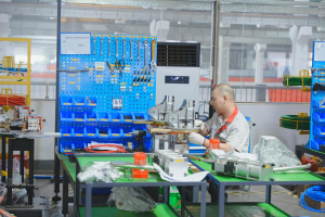
Resistance welding can present a range of production challenges, from unstable weld strength and incomplete welds on copper braided wires to roll-welding leaks, insufficient penetration in high-strength steel, and OEM traceability requirements. Based on Heron’s experience across automotive parts, low-voltage electrical, compressor, and sheet metal manufacturing, we’ve collected common resistance welding questions and practical ways to address them. The guide covers welding processes, equipment settings, and weld quality, with solutions engineers can use when troubleshooting issues on the production floor.

I. Resistance Welding: Common Weld Quality Problems
Q1: The weld looks intact, but the joint breaks easily during a tensile or bend test. What could be causing this?
An internal weak weld can result from gaps between parts, worn electrode tips, insufficient squeeze time, or current shunting. Multi-layer assemblies and closely spaced weld points are also more prone to this issue.
Solutions:
- Clean oil, dirt, and oxides from the part before welding.
- Increase squeeze time to close gaps before current is applied.
- Regularly dress electrode tips for flat contact surfaces.
- Maintain ≥30 mm weld spacing to reduce current shunting.
- Use MFDC welding for stable current control.
Q2: Air bubbles or voids appear inside the weld after welding. How can this be prevented?
Internal porosity forms when gas or vapor gets trapped within molten metal during solidification. It can arise from moisture, coating vaporization, and rapid cooling. Pressure-bearing components and automotive safety parts face elevated risks because porosity can affect joint strength and sealing performance.
Solutions:
- Use a controlled current profile rather than applying the full current immediately.
- Adjust the cooling rate to avoid excessive quenching of the weld area.
- Optimize the welding sequence and extend hold time to enable weld solidification under pressure.
- For roll welding, use intermittent current pulses where needed to reduce coating vaporization.
Q3: The sheet metal has excessive electrode indentation after welding. How can it be controlled?
Deep electrode indentation, more than 20% of the plate thickness, is usually caused by excessive electrode force, heat input, or an undersized electrode tip. Thin sheet and copper braided wire are particularly sensitive to deformation.
Solutions:
- Optimize electrode force, welding current and weld time together rather than tuning a single parameter.
- Use higher electrode force and shorter weld time where appropriate.
- Maintain stable electrode cooling to control heat accumulation during continuous welding.
- Select the correct electrode tip size and shape for the application.
- Inspect tips routinely to avoid uneven pressure and deep indentation.
Q4: Excessive spatter occurs during welding, and copper builds up on the electrode tips. What could be causing it?
Spatter is often related to excessive current, insufficient electrode force, poor adhesion, or unstable part contact. It is more prominent when welding galvanized sheets and high-strength steel. Copper buildup can further affect current distribution and weld consistency.
Solutions:
- Adjust welding current and electrode force.
- Ensure proper part alignment and clamping before welding.
- Periodically dress electrode tips to remove deposits and preserve tip geometry.
- Use automatic tip dressing for high-volume production.
- Evaluate welding parameters and electrode condition together instead of adjusting current in isolation.
II. Resistance Welding: Material and Process Compatibility
Q1: Why are copper braided wires and copper busbars difficult to weld consistently?
Copper has high electrical and thermal conductivity, which quickly spreads heat away from the weld area. Braided structures can also cause uneven contact and current distribution.
Solutions:
- Adopt capacitor discharge welding for a short, high-current pulse to concentrate weld heat.
- Use water-cooled chromium-zirconium-copper electrodes for stable electrode performance.
- Control electrode force; 200-500 N for copper braided wires can help avoid excessive compression of the conductor.
- Optimize current, pulse duration, and electrode force according to conductor dimension and joint design.
Q2: What makes high-strength steel and A-, B-, and C-pillar reinforcement panels difficult to weld?
High-strength and hot-formed steels require careful control of heat input to avoid excessive softening, cracking, or other changes in the heat-affected zone. Thickness variations and curved surfaces can also make electrode access and force control more difficult.
Solutions:
- Use gantry-type welding workstation with adjustable electrode positioning to reach weld points from different angles.
- Monitor key welding parameters, including current, voltage, and electrode force, to keep heat input within the required range.
- Implement stepped current profiles to regulate heat input and prevent overheating at individual welds.
Q3: Why do long sheet metal door rings often have missed or discontinuous welds during roll welding?
Unstable roller contact, mismatched travel speed and current timing, and pressure variations can cause missed welds and inconsistent weld spacing. Such defects produce weld gaps and impair sealing performance.
Solutions:
- Synchronize roller movement and current output with an encoder.
- Control travel speed and weld pitch according to joint requirements. For example, 15 m/min travel speed and 30 mm weld spacing can be used as starting parameters and adjusted through process validation.
- Use a dual-station layout where appropriate to reduce downtime and process variation.
Q4: Why is it difficult to achieve consistent welds between dissimilar materials such as steel and aluminum or copper and steel?
Different electrical and thermal properties can cause uneven heat distribution across the joint, making consistent bonding difficult.
Solutions:
- Use MFDC welding for precise current control.
- Select electrode materials and tip geometries for the materials being joined.
- Adjust current profile and weld sequence to control heat distribution.
- Optimize electrode force, current, and weld time together.
III. Resistance Welding Automation and Weld Quality Control
Q1: What if welding parameters need to be adjusted every time the part specification changes?
With conventional equipment, operators need to set up and verify welding parameters again when switching between products. Frequent parameter changes increase setup time and can lead to variation between batches.
Solutions:
- Store multiple welding programs in the welder and recall the correct program when changing products.
- Assign welding parameters to specific product or part numbers.
- Reduce setup time and avoid repeated trial welding during product changeovers.
- Keep welding parameters consistent across production batches.
Q2: What if an OEM requires weld point traceability, but the welding equipment does not record production data?
Many automotive OEMs require welding parameters to be recorded and traceable for quality audits and process verification. Without recorded welding data, it can be difficult to verify the conditions of individual weld points during quality audits.
Solutions:
Heron’s HRC Series Weld Monitoring System records key parameters such as welding current, electrode force, and weld time. Data can be stored, queried, and exported for weld traceability.
Q3: Can resistance welding equipment be integrated with robots for an automated production line?
Yes. Heron resistance welding equipment supports standard industrial communication interfaces and can exchange signals with robots and other line equipment. This allows loading, unloading, positioning, and welding to be integrated into an automated production line.
Q4: What if equipment failures and long repair times affect production?
Remote diagnostics can help reduce troubleshooting time. Engineers can access operating information and fault codes remotely to identify problems.
Heron resistance welding equipment provides monitoring and warning functions for conditions such as air pressure, cooling water temperature, and transformer status. Early warnings allow maintenance teams to address problems before they result in equipment downtime or component failure.
IV. Resistance Welding Cycle Time and Costs
Q1: The current welding cycle cannot keep up with the production line. How can throughput be increased?
First, review welding parameters and the cycle sequence to reduce unnecessary welding time. For higher production volumes, dual welding guns and dual-station layouts can run welding and loading or unloading in parallel, reducing idle time and increasing equipment utilization by more than 30%.
Q2: Electrode tips wear out quickly, resulting in high replacement costs. How can this be reduced?
Rapid electrode wear is often caused by insufficient tip dressing, poor cooling, or excessive heat input.
Solutions:
- Use automatic electrode tip dressing to maintain the correct tip geometry during production.
- Maintain stable cooling water flow and temperature to control electrode heat buildup.
- Optimize welding current, weld time, and electrode force to reduce overheating and electrode wear.
- Monitor electrode condition as part of routine preventive maintenance.
Q3: Can the same resistance welding machine handle both small-batch and high-volume production?
Yes, subject to machine configuration. A machine supporting both single-gun and dual-gun operation can suit both production scenarios. Deploy the single gun for prototyping or low-volume runs, then switch to dual-gun mode for higher throughput. This boosts production capacity without main machine replacement or additional standalone system investment.
V. Conclusion
Resistance welding quality depends on process parameters, workpiece condition, electrode maintenance, and equipment configuration—not just the welding machine. Different materials and applications require different welding parameters. Copper, high-strength steel, and stainless steel, for example, have different process requirements, while body panels, copper flexible connectors, and sealing door rings also differ in joint design. A suitable welding solution should therefore be selected based on the material, thickness, joint structure, weld requirements, and production rate.
If you are troubleshooting a resistance welding application, Heron can evaluate your part drawings, material specifications, weld requirements, and production targets. Our application engineers can recommend suitable welding parameters and equipment configurations based on the actual application.